

Precision Molding Techniques for Vehicle Components
Precision Injection Molding Drives Lighter, Stronger Automotive Parts
How can the automotive industry achieve both lightweight strength and high-volume precision at once? Injection molding forces molten polymer into a steel mold under pressure, creating complex parts like dashboards, bumpers, and interior trim in a single, rapid cycle. This process delivers unmatched repeatability and design flexibility, allowing engineers to consolidate multiple components into one integrated plastic assembly. Specify your automotive-grade resin, tool your steel cavity to micron tolerances, and you get a finished part ready for assembly without secondary machining.
Precision Molding Techniques for Vehicle Components
Precision molding for vehicle components demands tight tolerances, achieved through techniques like multi-stage injection and gas-assist molding to eliminate sink marks and warpage in complex geometries. High-cavitation tooling with conformal cooling channels ensures uniform heat dissipation, directly reducing cycle times while maintaining dimensional stability for critical parts like intake manifolds. In-mold sensor feedback systems enable real-time pressure and temperature adjustments, preventing flash and short shots in thin-wall structural components. This level of control allows molders to reliably produce Class A surfaces for interior trims without secondary finishing. Precision is further enforced by using hardened tool steels with micro-finished cavities, guaranteeing repeatable part release and longevity across high-volume production runs.
High-Strength Thermoplastics in Structural Parts
High-strength thermoplastics, such as carbon-fiber-reinforced PEEK and long-glass-fiber polypropylene, replace metal in structural parts like front-end modules and seat frames. Molding these materials demands precise control of melt flow to prevent fiber degradation, achieved through optimized gate placement and screw design. The critical cooling profile must avoid warpage while maintaining crystallinity for load-bearing integrity. A typical sequence for a structural bracket includes:
- Drying the resin to below 0.02% moisture.
- Injecting at high pressure (1500+ bar) to fill thin walls.
- Applying pack pressure above 80% of injection pressure to minimize sink marks.
- Controlled cooling at 10–15°C per minute to achieve target modulus.
Micro-Molding for Sensors and Electrical Housings
Within automotive precision molding, micro-molding for sensors and electrical housings delivers critical sub-millimeter tolerances for ADAS, radar, and LiDAR enclosures. This technique ensures airtight sealing against moisture and vibration via ultra-thin wall geometries and specialized high-temperature liquid crystal polymers. Micro inserts are overmolded with nanometer precision, eliminating signal interference while maintaining structural rigidity. The process enables complex internal channels for wire routing without flash, directly supporting miniaturized control units. Each housing withstands thermal cycling from -40°C to 150°C, locking component alignment within ±5 microns.
Gas-Assist Molding for Lightweight Assemblies
Gas-assist molding injects nitrogen into the molten plastic to create hollow cores within vehicle components, directly reducing material use and cycle times without sacrificing structural integrity. This technique excels in producing lightweight assemblies like door handles and mirror brackets, where targeted gas channels form internal ribs for rigidity while slashing weight. The process minimizes sink marks and warpage, enabling thinner wall sections that enhance fuel efficiency.Gas-assist molding for lightweight assemblies allows complex geometries impossible with solid injection, such as integrated air ducts in seating frames. Q: How does gas-assist molding improve part strength? A: It forces material against the mold walls, creating uniform density and eliminating weak spots, unlike conventional molding where voids occur randomly.
Material Innovations Driving Performance
In injection molding for the automotive industry, material innovations are driving performance by enabling parts that are simultaneously lighter, stronger, and more heat-resistant. High-performance polymers like PEEK and PPS replace metal in under-hood components, reducing vehicle weight while withstanding aggressive chemical and thermal stress. Advanced fillers, such as carbon fiber or graphene nanocomposites, enhance rigidity without sacrificing the thin-wall flow needed for complex geometries, directly improving fuel efficiency and crashworthiness.
These materials also reduce cycle times by up to 30% through optimized thermal conductivity, letting molds cool faster while maintaining tight dimensional tolerances for safety-critical chassis and powertrain parts.
Bio-based polyamides and self-reinforcing thermoplastics further push limits by offering mar resistance and UV stability for interior trim, all processed via standard molds.
Glass-Filled Nylon for Under-Hood Durability
Under the hood, components face extreme heat, vibration, and chemical exposure, where Glass-Filled Nylon for Under-Hood Durability proves indispensable. This material combines a polyamide base with short glass fibers, boosting tensile strength and stiffness to withstand engine bay thermal cycling and oil contact. Injection molders leverage its low moisture absorption to maintain dimensional stability in intake manifolds and valve covers. Its high heat deflection temperature prevents warping under continuous engine loads, while the glass reinforcement resists creep against fasteners. The result is lightweight, metal-replacing parts that retain structural integrity over thousands of driven miles.
Bio-Based Polymers for Eco-Conscious Interiors
Bio-based polymers for eco-conscious interiors derive from renewable sources like corn starch or castor oil, processed via injection molding to match conventional plastics’ mechanical performance. These materials reduce dependency on fossil fuels while offering lightweight properties that improve fuel efficiency. For automotive cabins, bio-based interior trim plastic injection molding automotive parts components achieve dimensional stability and surface finish required for dashboard panels or door inserts. The injection molding workflow adapts as follows:
- Drying the bio-polymer to precise moisture levels prevents hydrolysis during melting.
- Lower-temperature tooling maintains material integrity without thermal degradation.
- Controlled cooling rates ensure uniform shrinkage, avoiding warpage in complex geometries.
Such polymers enable direct replacement of petroleum-based resins without retooling production lines.
Liquid Silicone Rubber for Sealing Systems
Liquid Silicone Rubber for Sealing Systems offers superior thermal resistance and low compression set, enabling stable sealing under hood temperatures exceeding 200°C. Its high tear strength allows for complex, thin-wall geometries in static and dynamic seals without failure. The material’s inherent UV and ozone stability prevents degradation over long service intervals. Precision injection molding of LSR produces flash-free, tight-tolerance seals that consistently meet IP and dust ingress requirements. High-performance LSR sealing systems also demonstrate excellent chemical resistance to oils and coolants, ensuring leak-proof interfaces in powertrain and battery enclosures.
- Enables sub-0.5 mm wall thickness for weight reduction without compromising seal integrity.
- Self-lubricating surface properties reduce friction in dynamic wiper and piston seals.
- Fast cure cycles in injection molding minimize cycle time compared to solid silicone.
- Bonds directly to metal or plastic inserts during overmolding for integrated sealing solutions.
Tooling and Mold Design for High-Volume Production
In high-volume automotive production, tooling and mold design shifts from prototyping to relentless durability. We engineer multi-cavity molds with hardened steel and conformal cooling channels to cycle a thousand parts daily, shaving seconds off each shot. A single lift mechanism fails, and the entire line halts—so we nest slide actions within the B-plate to eject complex underhood brackets without interruption.
The mold literally becomes the bottleneck; its tolerance stack-up dictates whether a quarter-million headlamp housings seal without flash.
Every runner is balanced to the gram, and core pins are placed to pull vacuum during fill, ensuring uniform wall thickness across the shift. That’s the real context: the mold isn’t just shaped metal—it’s the rhythm of the factory floor.
Conformal Cooling Channels to Reduce Cycle Times
In high-volume automotive tooling, conformal cooling channels to reduce cycle times follow the complex geometry of a mold cavity, unlike conventional straight-line drilling. By maintaining uniform heat transfer across the part, these channels minimize hot spots and residual stress. This targeted cooling can slash cycle times by 15–30% in thick-section components like dash panels or bumpers. The uniform thermal profile also reduces part warpage, improving dimensional consistency across production runs.
- Follow cavity contours within 1–2 mm to extract heat from complex geometries.
- Employ additive manufacturing or U-shaped milling to achieve conformal paths.
- Require optimized flow rate and temperature analysis to avoid cooling bottlenecks.
Multi-Cavity Molds for Dashboard Overlays
For high-volume production of dashboard overlays, engineers specify multi-cavity molds to maximize output per cycle. These tools incorporate strategically placed runners and balanced gate designs—typically edge or fan gates—to ensure uniform material flow across all cavities. The list sequence for optimization is:
- Select cavity count based on press tonnage and overlay size.
- Design conformal cooling channels to prevent warpage in large, thin-wall parts.
- Implement hot runner systems for precise melt control and reduced scrap.
This approach crams parallel processing into a single clamp stroke, slashing cycle time without sacrificing the dimensional stability required for dashboard overlays.
Hot Runner Systems for Waste Minimization
In automotive tooling and mold design for high-volume production, hot runner systems directly minimize waste by eliminating the solidified material in the runner channels required by cold runner molds. These systems maintain the plastic in a molten state within the manifold and nozzle, delivering material directly to the cavity gate. This approach removes the need for post-mold regrinding of sprues and runners, which is critical for high-volume automotive parts where even minor material loss compounds significantly. Using a hot runner can reduce scrap rates to near zero for stable processes. This design achieves substantial material savings in automotive production by ensuring every shot of plastic forms a usable part, optimizing resource use and lowering per-part costs through reduced waste handling.
Quality Control Standards in Automotive Parts
In injection molding for automotive industry, quality control standards hinge on dimensional precision and material consistency. Every part must meet strict tolerances, often verified through CMM (coordinate measuring machine) spot-checks and real-time process monitoring. A common checkpoint is the “first article inspection” (FAI), which validates a mold’s output before full production begins. Q: How do you catch defects during a run? A: Sensors track melt temperature, pressure, and cooling times; any deviation flags a potential warp or short shot. Regular pull tests confirm that resins—like reinforced nylon or PP—maintain tensile strength, ensuring parts won’t fail under hood heat. This keeps each dashboard clip, bracket, or sensor housing reliable from assembly line to end user.
Automated Inspection for Dimensional Accuracy
Automated inspection for dimensional accuracy in automotive injection molding leverages high-speed laser scanners and machine vision to instantly verify critical part geometries against CAD models. This real-time feedback loop allows press operators to detect micron-level deviations in features like mounting bosses or snap-fits during the molding cycle, preventing scrap cascades. The core advantage lies in real-time dimensional feedback, which eliminates manual check delays and ensures every cycle produces components within tight tolerance windows. This direct integration with the molding cell enables immediate corrective adjustments to process parameters.
- Laser triangulation probes measure flatness and warpage on complex curved surfaces as parts exit the tool.
- Multi-camera vision systems simultaneously verify hole positions, diameters, and edge profiles across the entire shot.
- Inline optical comparators capture full perimeter outlines to detect flash or sink marks affecting fit.
X-Ray and CT Scanning for Hidden Cavities
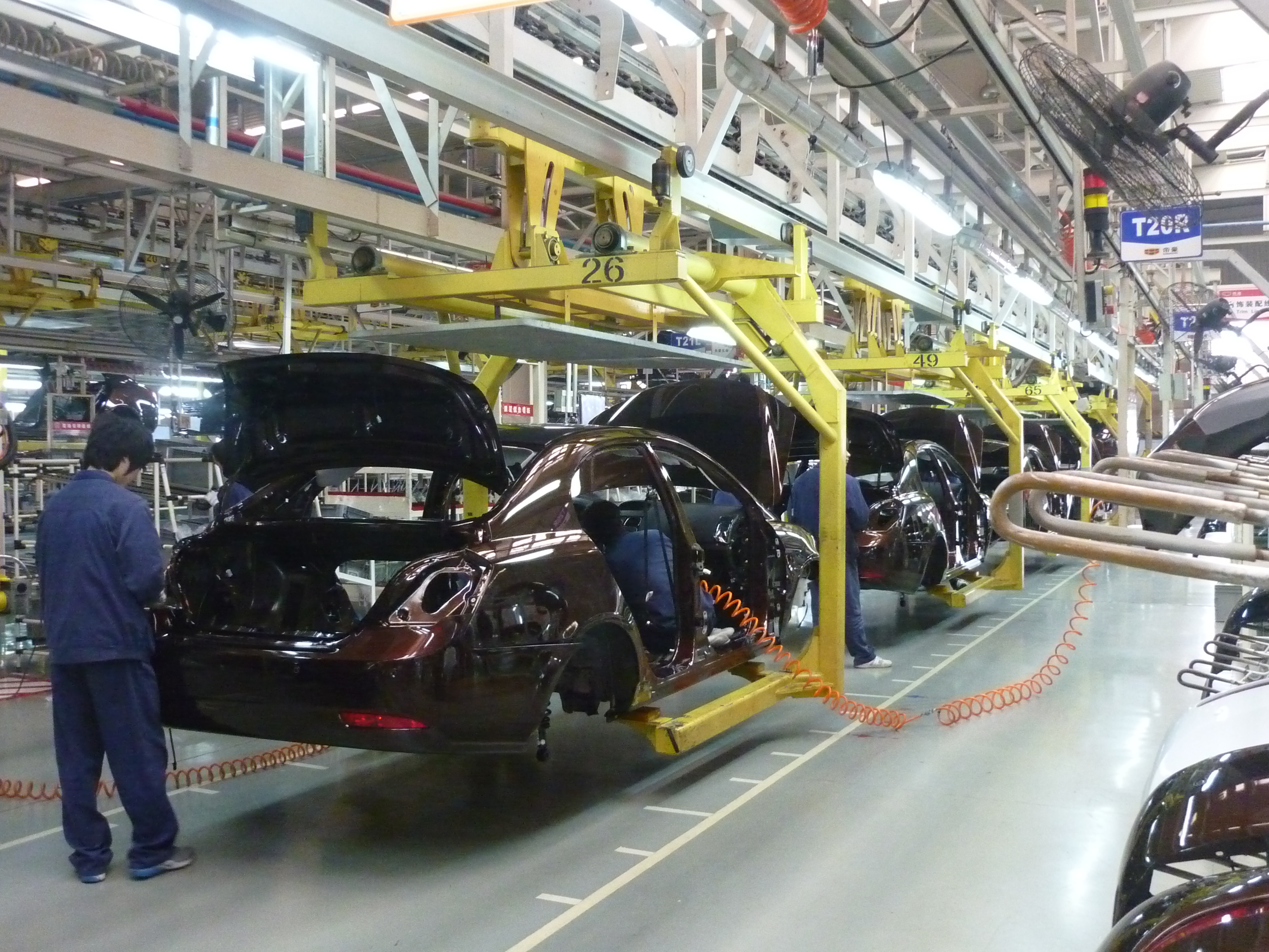
X-ray and CT scanning are critical for detecting hidden cavities within complex automotive injection moldings, such as internal coolant channels or blind fastening points. These non-destructive methods create high-resolution cross-sections, revealing subsurface voids, porosity, or incomplete fill that visual inspection misses. For safety-critical parts like air intake manifolds, CT scanning validates internal geometry against design specs, ensuring flow paths remain unobstructed and wall thicknesses meet durability requirements. This precision catches defects before assembly, preventing costly field failures in fluid or structural systems.
X-ray and CT scanning expose hidden cavities in injection-molded automotive parts, verifying internal structures are sound and free of voids or porosity.
Real-Time Process Monitoring During Production
Real-time process monitoring during production keeps injection molding for automotive parts on track by tracking cavity pressure, temperature, and fill speed as they happen. This data lets operators catch flash or short shots instantly, preventing defective batches. A simple dashboard alert for viscosity shifts can mean the difference between a usable trim piece and scrap. Automated adjustments, like tweaking clamp force mid-cycle, maintain dimensional stability. Real-time adaptive control reduces waste and ensures each part meets tight tolerances without waiting for lab results.
Real-time process monitoring watches every shot’s key metrics live, letting you fix issues on the fly and keep quality consistent throughout the run.
Cost Efficiency Through Advanced Manufacturing
Advanced manufacturing slashes per-part costs in automotive injection molding by integrating real-time process monitoring to eliminate scrap and reduce cycle times. Multi-cavity and family mold designs maximize output per press shot, directly lowering unit expense for high-volume components. Additive-manufactured conformal cooling channels enable faster, more uniform heat extraction, yet require precise thermal simulation to avoid warpage that erodes thin-margin savings. By automating material handling and robotic part removal, facilities cut labor overhead while achieving repeatable micron-level precision that reduces post-molding finishing costs.
Nickel Shell Molds for Rapid Prototyping
Nickel shell molds for rapid prototyping drastically slash lead times and tooling costs for automotive injection molding. Instead of machining solid steel, a thin, electroformed nickel shell is deposited onto a precise pattern, creating a durable cavity that withstands tens of thousands of production-grade cycles. This method enables functional validation of complex geometries—like air intake ducts or sensor housings—without investing in expensive hardened steel. Surface finishes mirror the master pattern, reducing post-processing. How quickly can a nickel shell mold be produced for automotive parts? Typically within 10–15 business days, versus weeks for conventional tooling, accelerating design iterations while maintaining tight tolerances.
Recycled Thermoplastics in Non-Safety Components

Using recycled thermoplastics for interior trim and under-hood covers directly reduces material costs without compromising performance. These non-safety components tolerate the slight variability in mechanical properties that recycled blends introduce. You can maintain tight dimensional tolerances by adjusting mold shrinkage calculations for the recycled feedstock. The process benefits from consistent flow characteristics, though you must pre-dry hygroscopic materials to prevent surface defects. This approach slashes raw material expenditure while supporting closed-loop manufacturing cycles, making it a practical choice for high-volume interior parts like dashboard brackets and door panels.
Lean Production Flow in Tier-One Supplier Plants
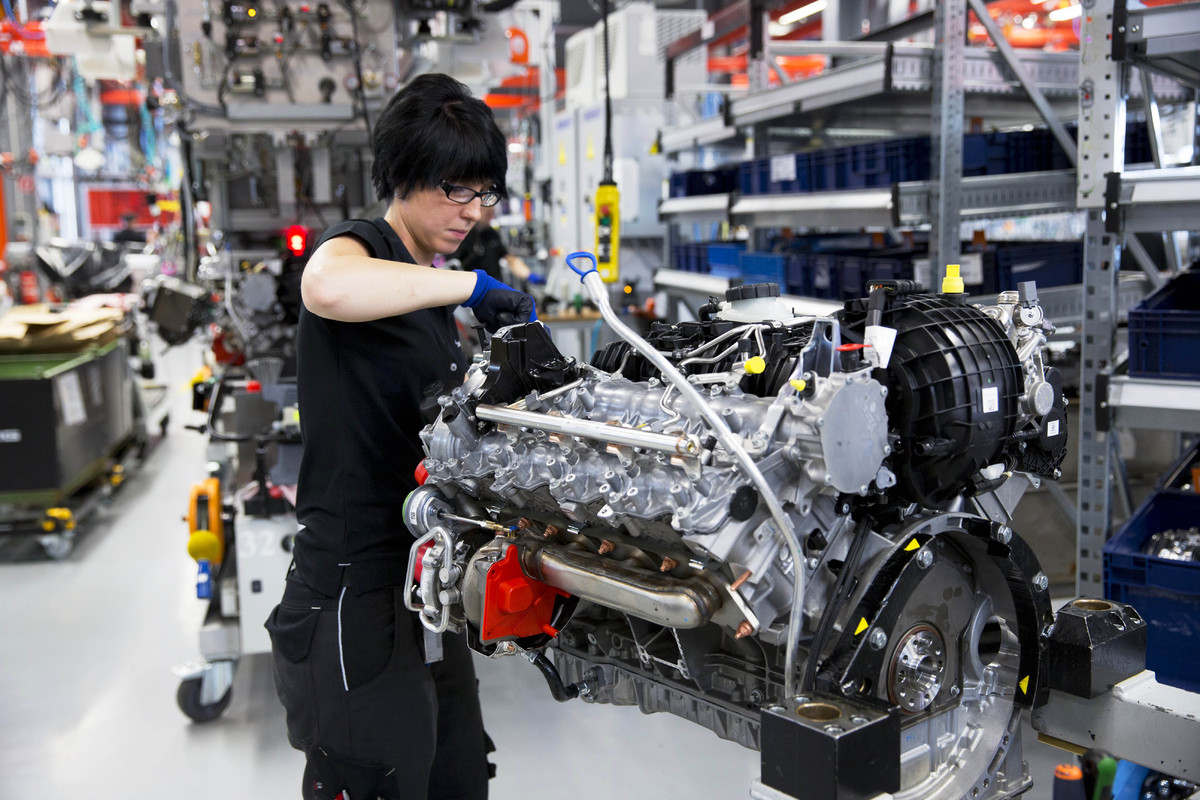
In tier-one supplier plants, lean production flow in injection molding eliminates waste by synchronizing press cycles with downstream assembly. Single-minute exchange of dies reduces changeover times, allowing small-lot production that directly responds to OEM just-in-time demands. Cellular layouts place injection presses adjacent to trimming and inspection stations, preventing WIP pileups. Pull systems trigger material replenishment only when a downstream bin empties, slashing inventory carrying costs. Every operator’s standard work supports continuous flow, from pellet drying through finished part boxing.
Q: How does lean production flow reduce costs in tier-one injection molding?
A: It eliminates non-value-added transport, waiting, and overproduction by linking press cycles directly to assembly demand, cutting labor and floor space while raising first-pass yield.
Surface Finishing and Aesthetic Integration
In automotive injection molding, surface finishing and aesthetic integration go beyond just making parts look good—they ensure textures, grain patterns, and color match across different trim pieces like door panels or dashboards. Molds are often textured via chemical etching or laser engraving to replicate leather or soft-touch feels, while in-mold decoration (IMD) bonds film graphics directly during molding for seamless logos or wood grain.
Key insight: Achieving zero-gloss mismatch between adjacent panels requires precise control of mold polishing and gate placement to prevent flow lines from disrupting uniformity.
Even subtle matte or gloss levels must be locked in by adjusting injection speed and melt temperature, avoiding sink marks that ruin the premium look automakers demand.
In-Mold Decoration for Trim and Grilles
For automotive trim and grilles, in-mold decoration (IMD) eliminates post-molding painting by fusing a printed film directly during injection. This process embeds metallic finishes, chrome-look gradients, or intricate textures beneath a durable top layer. A precise sequence ensures flawless results: first, a carrier film is pre-formed to match the cavity; second, the film is placed and held via vacuum; third, molten resin bonds behind it, locking the decoration in place. This yields grilles with scratch-resistant, UV-stable surfaces and seamless edge wraps that resist chipping. Because the decorative layer is protected, trim parts retain showroom gloss through years of weather exposure.
Texture Stippling to Reduce Glare on Dashboards
Texture stippling directly addresses dashboard glare by engineering microscopic peaks and valleys into the injection-molded surface. This micro-texture diffuses reflected light, eliminating harsh specular highlights that impair driver vision. Anti-glare stippling patterns are precisely machined into the mold cavity, ensuring every part replicates the light-diffusing structure without post-processing. Pitch depth and density must be calibrated to the dashboard’s viewing angle to maximize scatter without trapping dust. Unlike smooth finishes that amplify dashboard reflections, stippling achieves a matte, durable surface that withstands UV exposure and abrasion from cleaning.
Two-Shot Molding for Soft-Touch Overmolds
Two-shot molding for soft-touch overmolds integrates a rigid thermoplastic substrate with a thermoplastic elastomer (TPE) in a single cycle, eliminating secondary assembly. In automotive interiors, this process bonds a durable, non-slip layer directly onto components like door handles and steering wheel controls, ensuring permanent adhesion without adhesives. The overmold thickness typically ranges from 1–3 mm for optimal tactile feel. Cavity-specific hardness gradients can be achieved by varying TPE Shore values between 30A and 70A across the same part. Key parameters include precise injection sequencing to avoid flashing and matching melt temperatures within 10°C to prevent material degradation. This method also seals exposed edges, reducing moisture ingress and wear points.
| Aspect | Two-Shot Soft-Touch |
|---|---|
| Cycle Time | Single press cycle (no handling steps) |
| Bond Strength | Chemical/thermal fusion (no primer required) |
| Surface Texture | Matte, anti-slip, or micro-grip patterns |
Future Trends Shaping Plastic Fabrication

The latest shift in automotive injection molding involves multi-material overmolding, where a single cycle bonds soft TPEs onto rigid nylon for integrated sealing and vibration dampening. This eliminates secondary assembly of gaskets and bushings, reducing part count and potential failure points. Q: What is the core advantage of this trend? A: It creates hybrid components with tailored properties in one shot. Simultaneously, rapid induction heating of molds allows the use of high-flow, glass-reinforced thermoplastics for structural crash absorbers, previously limited to metal. These flowing materials fill thin-wall geometries without weld lines, enabling a single molded frame that replaces a stamped assembly of ten separate steel brackets.
Hybrid Metal-Polymer Parts for EV Battery Housings
Hybrid metal-polymer parts for EV battery housings leverage overmolding to bond a continuous metal insert with a flame-retardant polymer, creating an integrated structural shell that provides both electromagnetic shielding and thermal management. Selective metal-polymer interfaces allow designers to place conductive pathways precisely for cell monitoring circuits without secondary assembly. The polymer component absorbs vibrational loads while the metal insert acts as a heat spreader. This co-molding approach eliminates separate gaskets and fasteners, reducing leak paths in sealed enclosures.
| Aspect | Hybrid Approach |
|---|---|
| Thermal Conductivity | Metal insert: 150–400 W/mK; polymer pockets: <1 w mk< td> |
| EMI Shielding | Metal provides full Faraday cage; polymer is transparent to frequencies |
| Weight Reduction | 30–50% lighter than all-metal housing |
| Cycle Time | Extended by preheat and insert placement step |
Additive Manufacturing for Custom Tooling Inserts
Additive manufacturing enables the production of custom tooling inserts with complex internal conformal cooling channels, directly reducing cycle times in automotive injection molding. These inserts, often printed in maraging steel or copper alloys, allow for rapid heat dissipation in high-stress areas like ribs or bosses. This targeted thermal management mitigates warpage in large parts such as dashboards or bumpers. The process supports iterative design for in-mold sensors, permitting real-time cavity pressure monitoring without post-machining. By swapping only the insert rather than the entire mold, manufacturers can optimize localized heat distribution for variable wall-thickness components, improving dimensional stability across production runs.
Additive manufacturing provides custom tooling inserts that integrate conformal cooling and sensor ports, enhancing part quality and cycle efficiency in automotive molds.
Digital Twin Simulations for Mold Flow Analysis
Digital twin simulations for mold flow analysis enable precise prediction of polymer behavior within a virtual cavity, eliminating physical trial-and-error for automotive injection molding. The sequence begins with building a high-fidelity digital twin from exact CAD and material property data, then running iterative simulations to visualize melt front advancement, weld line positions, and volumetric shrinkage. Predictive defect resolution follows, where the simulation flags potential gas traps or excessive shear stress without requiring steel modifications. Finally, engineers adjust gate locations and cooling channel layouts within the twin to achieve uniform packing and cycle time reduction. This closed-loop digital validation converges on optimal process parameters before a single mold is cut.

